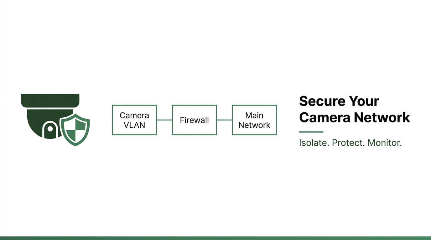
A separate VLAN for IP cameras is a dedicated Layer 2 network segment, defined by the IEEE 802.1Q standard, that isolates surveillance traffic from production systems to strengthen security, optimize bandwidth, and contain firmware exploits.
This guide covers network segmentation fundamentals, equipment selection and IP addressing, managed switch and inter-VLAN routing configuration, post-migration verification and troubleshooting, VLAN hardening against cyber threats, and AI-powered live monitoring integration.
Placing cameras on their own VLAN creates a micro-segmented broadcast domain where compromised devices cannot pivot to file servers, point-of-sale terminals, or domain controllers. Host authentication and firewall rules lock down lateral movement at the network layer.
Bandwidth isolation prevents high-volume 4K streams from competing with VoIP, email, or cloud applications. Pairing VLAN segmentation with H.265 compression cuts per-camera throughput roughly in half, while Multicast VLAN Registration conserves upstream capacity across multi-camera deployments.
The hardware foundation requires a managed switch with PoE support (802.3at or 802.3bt depending on camera wattage), a VLAN-capable firewall for inter-VLAN routing, and a dedicated subnet mapped 1:1 to the VLAN ID. Proper trunk port tagging and DHCP relay configuration prevent the connectivity failures that most commonly surface during migration.
Hardening the finished VLAN involves blocking outbound internet access, restricting management to designated workstations, and monitoring traffic baselines with SNMPv3 and NetFlow. These controls transform segmentation from a passive boundary into an active detection layer.
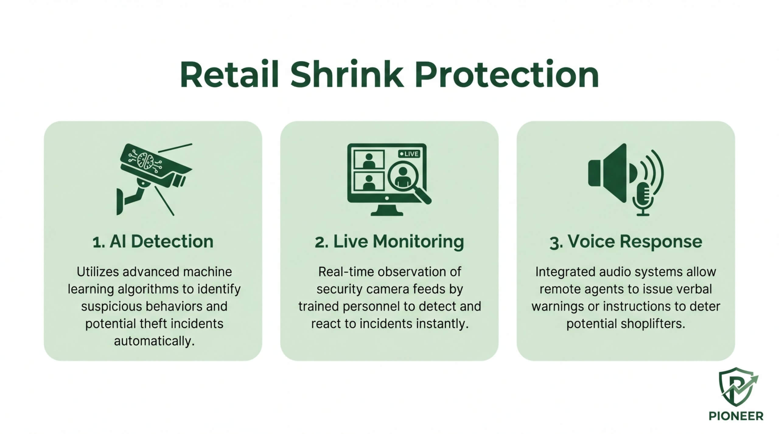
Layering AI-powered live video monitoring on top of a secured VLAN adds real-time human threat verification, closing the gap between network isolation and actionable incident response.
Why Should You Put IP Cameras on a Separate VLAN?
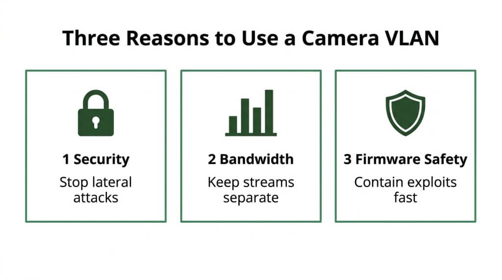
You should put IP cameras on a separate VLAN to isolate surveillance traffic from your main network, improving security, bandwidth performance, and firmware exploit containment. The following sections cover each benefit in detail.
How Does a Camera VLAN Improve Network Security?
A camera VLAN improves network security by isolating surveillance devices into a dedicated Layer 2 broadcast domain, preventing compromised cameras from reaching sensitive business systems. VLAN-based segmentation operates as a network micro-segmentation construct defined by the IEEE 802.1Q standard, designed to improve both security and bandwidth utilization, according to IEEE Access.
Maintaining a 1:1 relationship between VLANs and subnets is considered a best practice among IT professionals for clean network organization. Hardening measures become more effective within this isolated segment; host authentication can block access from any location other than registered IP addresses. Without segmentation, a single breached camera could serve as a lateral entry point into file servers, point-of-sale terminals, or access control systems. Dedicating a VLAN to cameras eliminates that pathway at the network layer.
How Does a Dedicated VLAN Reduce Bandwidth Congestion?
A dedicated VLAN reduces bandwidth congestion by confining high-volume video streams to their own broadcast domain, preventing camera traffic from competing with business-critical applications. Surveillance footage, particularly at 4K resolution, generates substantial and constant data flow that can saturate a shared network.
Pairing VLAN isolation with modern compression amplifies the benefit. According to ASI Networks, switching from H.264 to H.265 compression can reduce bandwidth requirements for a 4K camera from 8–12 Mbps down to 4–6 Mbps. For multi-camera deployments, Multicast VLAN Registration allows a Layer 2 switch to forward multicast data from a source VLAN to multiple subscriber VLANs, conserving upstream bandwidth. Together, these strategies keep video traffic contained and efficient without degrading VoIP, email, or cloud application performance.
How Does VLAN Segmentation Protect Against Firmware Exploits?
VLAN segmentation protects against firmware exploits by containing vulnerable cameras within a logically isolated network segment, so an exploited device cannot communicate with systems outside its assigned VLAN. As specified by IEEE 802.1Q, VLAN tagging inserts a 32-bit field into Ethernet frames to identify VLAN membership, enforcing this boundary at the frame level.
IP cameras often run embedded firmware that receives infrequent patches, making them persistent targets. When a camera with an unpatched vulnerability sits on a segmented VLAN, attackers who exploit that firmware gain access only to the camera subnet. They cannot pivot to databases, workstations, or domain controllers without passing through a firewall or router with explicit inter-VLAN rules. This containment strategy is one of the most practical defenses for any organization running IoT surveillance devices.
With security, bandwidth, and exploit containment addressed, the next step is selecting the right equipment.
What Equipment Do You Need to Create a VLAN for IP Cameras?
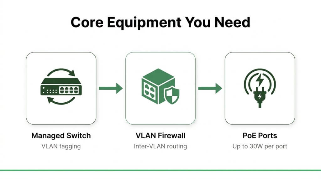
The equipment you need to create a VLAN for IP cameras includes a managed network switch, a VLAN-capable router or firewall, and PoE-rated ports matching your camera power demands. The sections below cover each component.
What Kind of Network Switch Supports VLANs?
The kind of network switch that supports VLANs is a managed switch with IEEE 802.1Q VLAN tagging capability. Unmanaged switches cannot create or assign VLAN IDs, making them unsuitable for segmented camera networks.
Key features to look for in a VLAN-capable managed switch include:
- IEEE 802.1Q VLAN tagging support for logical network segmentation.
- Configurable access ports and trunk ports for proper traffic handling.
- A web-based or CLI management interface for VLAN creation and port assignment.
- Sufficient port density to accommodate all cameras plus uplink connections.
According to a 2025 TechRadar review, the Cisco CBS350-8MGP-2X ranks among the top-performing managed switches, offering PoE and VLAN support suited for small-scale surveillance deployments. For most camera installations under 16 channels, a managed switch in this class provides the right balance of functionality and cost.
Do You Need a VLAN-Capable Router or Firewall?
Yes, you need a VLAN-capable router or firewall to enable communication between the camera VLAN and other network segments. A managed switch isolates camera traffic at Layer 2, but without a routing device, the NVR or VMS on your main network cannot access camera feeds.
VLAN-capable routers and firewalls serve two critical functions:
- They perform inter-VLAN routing so authorized devices can reach the camera subnet.
- They enforce firewall rules that block unauthorized or outbound internet traffic from cameras.
Devices like pfSense, UniFi Security Gateways, and Cisco routers support VLAN subinterfaces for this purpose. A firewall is generally the better choice over a basic router because it combines routing with granular access control in a single appliance.
What PoE Requirements Should the Switch Meet for IP Cameras?
The PoE requirements the switch should meet for IP cameras depend on camera resolution and feature set. Standard fixed cameras typically draw under 15W, while PTZ and 4K models need significantly more power.
The three main PoE standards relevant to IP cameras are:
- IEEE 802.3af (PoE): Delivers up to 15.4W per port, sufficient for basic fixed cameras.
- IEEE 802.3at (PoE+): Delivers up to 30W per port, suitable for 4K cameras and PTZ devices.
- IEEE 802.3bt (PoE++): Delivers up to 90W per port using all four twisted-pair cables, designed for high-power accessories.
According to Phihong’s PoE standards guide, IEEE 802.3at (PoE+) provides up to 30W, which covers most advanced 4K IP cameras and PTZ devices. Beyond per-port wattage, verify the switch’s total PoE power budget; a 16-port switch powering twelve 25W cameras needs at least 300W of aggregate PoE capacity.
With the right switch, router, and PoE specifications selected, the next step is planning the IP address scheme for your camera VLAN.
How Do You Plan IP Address Schemes for a Camera VLAN?
You plan IP address schemes for a camera VLAN by assigning a dedicated subnet, reserving a static IP range for cameras, and configuring a separate DHCP scope. These three steps prevent address conflicts and simplify device management.
What Subnet Should You Assign to the Camera VLAN?
The subnet you should assign to the camera VLAN is a dedicated private IP range that maps 1:1 to the VLAN ID. A common approach uses 10.10.[VLAN_ID].0/24, so VLAN 50 becomes 10.10.50.0/24. This convention keeps addressing intuitive as systems scale.
A /24 subnet provides 254 usable host addresses, which accommodates most surveillance deployments with room for growth. For larger installations exceeding 200 cameras, a /23 subnet doubles available addresses to 510.
Key subnet planning considerations include:
- Avoid overlapping with existing network subnets used by workstations, servers, or guest Wi-Fi.
- Reserve the first address (e.g., 10.10.50.1) as the default gateway on your router or Layer 3 switch interface.
- Document the subnet assignment in your network diagram to prevent future conflicts.
If cameras will obtain addresses via DHCP from a server on another VLAN, a DHCP relay agent is required to forward requests across subnet boundaries, according to Extreme Networks documentation.
How Do You Set a Static IP Range for IP Cameras?
You set a static IP range for IP cameras by reserving a contiguous block of addresses within the camera subnet exclusively for camera devices. Static assignments ensure each camera retains a consistent address, which simplifies NVR configuration and troubleshooting.
A practical allocation for a 10.10.50.0/24 subnet:
- Cameras: 10.10.50.10 through 10.10.50.199
- NVR/VMS servers: 10.10.50.200 through 10.10.50.210
- Network infrastructure (switches, access points): 10.10.50.240 through 10.10.50.254
Assign addresses sequentially by physical location or floor to make identifying devices straightforward during maintenance. Label each camera’s IP in both the NVR software and a centralized spreadsheet. Consistent static addressing eliminates the risk of feed disruptions caused by IP lease changes, which is especially critical for systems feeding into 24/7 monitoring platforms.
Should the Camera VLAN Use a Separate DHCP Scope?
Yes, the camera VLAN should use a separate DHCP scope if you manage cameras through dynamic addressing or need automated provisioning during initial deployment. A dedicated scope isolates camera address allocation from other network segments, preventing pool exhaustion or accidental cross-assignment.
When configuring the scope, include these parameters:
- Address range: Match the reserved camera block (e.g., 10.10.50.10 to 10.10.50.199).
- Default gateway: The camera VLAN’s router interface (e.g., 10.10.50.1).
- DNS server: Only if cameras require name resolution; many deployments leave this blank for security.
- Lease duration: Set longer leases (7+ days) since cameras remain connected continuously.
Trunk port misconfiguration between the switch and DHCP server is a common cause of scope failures, often involving mismatched native VLANs or incorrect allowed VLAN lists, as documented in Cisco Community troubleshooting cases. Verify trunk settings before testing the scope.
For maximum reliability, many installers use DHCP reservations rather than pure static entries; this combines centralized management with consistent addressing. With a well-structured IP scheme in place, the next step is configuring the VLAN on your managed switch.
How Do You Configure the VLAN on a Managed Switch?
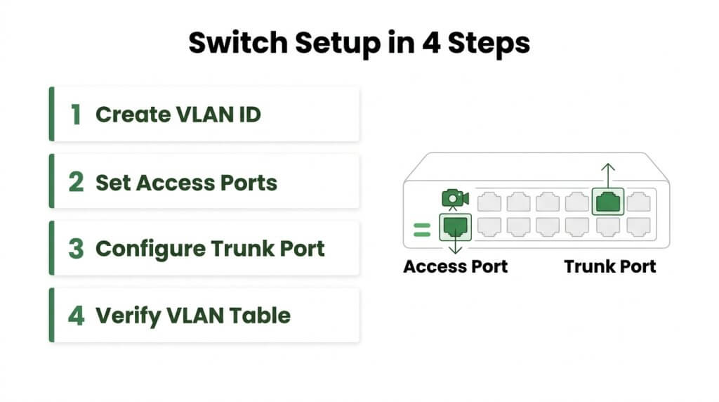
You configure the VLAN on a managed switch by creating a VLAN ID, assigning camera ports as access ports, and configuring the uplink as a trunk port. The following steps cover VLAN creation, port assignment, access versus trunk differences, and trunk configuration.
How Do You Create a New VLAN ID on the Switch?
You create a new VLAN ID on the switch by accessing the management interface and defining a unique numeric identifier for the camera network. Most managed switches support VLAN creation through a web GUI or command-line interface. The process involves these core steps:
- Log into the switch management interface using the admin credentials.
- Navigate to the VLAN configuration section.
- Enter a VLAN ID number, such as 100 or 200, that does not conflict with existing VLANs.
- Assign a descriptive name like “IP_Cameras” for easy identification.
- Save the configuration and confirm the new VLAN appears in the VLAN table.
According to TechRadar, the Cisco CBS350-8MGP-2X is identified as a top-performing managed switch for 2025, offering PoE support suitable for small-scale surveillance deployments. Choosing a switch with a clean management interface simplifies this entire process considerably.
How Do You Assign Switch Ports to the Camera VLAN?
You assign switch ports to the camera VLAN by configuring each port connected to an IP camera as an access port within the designated VLAN ID. This ensures every frame leaving that port carries the correct VLAN membership.
Set each camera-facing port to “access” mode and specify the camera VLAN number. Equally important is disabling unused ports and setting all camera ports to static access mode rather than leaving them in negotiation states. A study published on ResearchGate found that VLAN hopping attacks can occur due to misconfigurations such as leaving ports in “Dynamic Desirable” mode, which allows unauthorized trunking. Hardening each port to a fixed access state eliminates this risk.
What Is the Difference Between Access Ports and Trunk Ports?
The difference between access ports and trunk ports is how they handle VLAN-tagged traffic. Access ports belong to a single VLAN and strip all VLAN tags from frames, making them ideal for end devices like IP cameras. Trunk ports, by contrast, carry traffic for multiple VLANs simultaneously by preserving 802.1Q tags on each frame.
- Access ports connect to cameras, computers, or other single-VLAN devices.
- Trunk ports connect switches to routers, firewalls, or other switches that need multi-VLAN communication.
- Access ports send and receive untagged frames only.
- Trunk ports send and receive tagged frames across all allowed VLANs.
For a camera VLAN setup, every port with a camera plugged in should be an access port, while the uplink to the router or core switch should be a trunk port.
How Do You Configure the Uplink Trunk Port for the Camera VLAN?
You configure the uplink trunk port for the camera VLAN by setting the designated uplink port to trunk mode and specifying which VLANs are permitted to traverse it. Only allow the VLANs that genuinely need to communicate through this link; restrict everything else.
Key configuration steps include:
- Set the uplink port mode to “trunk.”
- Define the allowed VLAN list to include the camera VLAN and any management VLANs.
- Set the native VLAN to a dedicated, unused VLAN ID rather than VLAN 1.
- Verify that the native VLAN matches on both ends of the trunk link.
According to Cisco Community documentation, trunk port misconfiguration is a common cause of connectivity loss in inter-VLAN routing setups, often involving mismatched native VLANs or allowed VLAN lists. Verifying consistency on both sides of every trunk prevents most connectivity failures before they start.
With the switch fully configured, the next step is setting up inter-VLAN routing so your NVR or VMS can reach the camera subnet.
How Do You Set Up Inter-VLAN Routing for Camera Access?
You set up inter-VLAN routing for camera access by creating a Layer 3 interface for the camera VLAN, writing targeted firewall rules, and selectively permitting NVR or VMS traffic. The following sections cover each step.
How Do You Create a VLAN Interface on the Router or Firewall?
You create a VLAN interface on the router or firewall by configuring a Layer 3 logical interface that serves as the default gateway for your camera subnet. According to Juniper Networks documentation, forwarding packets between VLANs requires an Integrated Routing and Bridging (IRB) interface or a dedicated router to connect the logical segments.
Two common approaches exist:
- Router-on-a-stick: Create a subinterface on the router’s physical port, assign it the camera VLAN ID and subnet gateway IP.
- Switch Virtual Interface (SVI): On a Layer 3 switch, create an SVI tied to the camera VLAN ID and assign the gateway address directly.
Assign the interface an IP within the camera subnet, such as 10.10.20.1/24, so cameras use it as their default gateway. For most small-to-midsize surveillance deployments, the SVI method on a Layer 3 switch offers simpler management and lower latency than routing through a separate device.
How Do You Write Firewall Rules Between the Camera and Main VLANs?
You write firewall rules between the camera and main VLANs by creating explicit allow and deny policies on your router or firewall’s inter-VLAN access control list. IPVM recommends maintaining a 1:1 relationship between VLANs and subnets, which simplifies rule targeting.
Effective rules follow these principles:
- Default deny: Block all traffic between the camera VLAN and other VLANs by default.
- Selective allow: Permit only the specific ports your NVR or VMS requires, such as RTSP (554), ONVIF (80/8080), and HTTPS (443).
- Direction matters: Apply inbound rules on the camera VLAN interface to filter traffic at the source before it crosses into other segments.
This approach ensures cameras remain reachable for authorized management while preventing lateral movement across the broader network.
How Do You Allow NVR or VMS Traffic While Blocking Internet Access?
You allow NVR or VMS traffic while blocking internet access by combining a targeted permit rule with a broad outbound deny rule on the camera VLAN interface. First, create a rule permitting traffic from the camera subnet to the NVR or VMS host IP on required ports only. Then add a deny rule that blocks all remaining traffic from the camera subnet to any destination, including the WAN gateway.
The rule order matters:
- Permit camera subnet to NVR/VMS IP on ports 554, 80, and 443.
- Permit DHCP and DNS if cameras need dynamic addressing or hostname resolution.
- Deny camera subnet to any destination (this catches internet-bound traffic).
Blocking outbound internet access is one of the most effective hardening steps for a camera VLAN, since compromised cameras cannot phone home to external command-and-control servers. With routing and firewall policies configured, connecting cameras and verifying feeds on the new VLAN is the next step.
How Do You Connect IP Cameras and NVR to the New VLAN?
You connect IP cameras and NVR to the new VLAN by plugging cameras into assigned access ports, configuring the NVR’s network interface for cross-VLAN communication, and verifying feeds post-migration. The following steps cover port assignment, NVR routing, and feed verification.
How Do You Assign Cameras to the Correct VLAN Port?
You assign cameras to the correct VLAN port by connecting each camera’s Ethernet cable to a switch port already configured as an access port on the camera VLAN ID. Before plugging in, confirm the port assignment in the switch management interface.
Follow this process for each camera:
- Label each camera cable with its intended port number for easy identification.
- Connect the camera to the designated PoE-enabled access port on the managed switch.
- Verify the port’s VLAN membership in the switch dashboard to confirm it belongs to the camera VLAN, not the default VLAN.
- Check that the camera receives a valid IP address from the camera VLAN’s DHCP scope or assign a static IP within the correct subnet.
Leaving any port on the default VLAN is one of the most common oversights during migration, so always double-check before moving to the next camera.
How Do You Configure the NVR to Communicate Across VLANs?
You configure the NVR to communicate across VLANs by placing it on the main network VLAN and routing traffic to the camera VLAN through inter-VLAN routing rules on your router or Layer 3 switch. The NVR needs a gateway address that points to the router interface handling cross-VLAN forwarding.
Key configuration steps include:
- Set the NVR’s IP address within the main VLAN subnet, with the default gateway pointing to the router’s VLAN interface.
- Confirm that firewall rules permit traffic from the NVR’s IP to the camera subnet on required ports, such as RTSP (554) and ONVIF (80/8080).
- Block all other traffic between VLANs to maintain segmentation integrity.
According to Juniper Networks, an Integrated Routing and Bridging (IRB) interface or a dedicated router is required to forward packets between VLANs. Without this routing layer, the NVR simply cannot discover or pull streams from cameras on a separate VLAN.
How Do You Verify Camera Feeds After VLAN Migration?
You verify camera feeds after VLAN migration by systematically checking each camera’s connectivity, stream quality, and recording status from the NVR interface. A structured verification process catches issues before they become blind spots in your coverage.
Complete these checks for every camera:
- Open the NVR’s live view and confirm each camera displays its feed without latency or artifacts.
- Ping each camera’s IP address from the NVR to confirm cross-VLAN routing is functional.
- Trigger a test recording and verify playback to ensure the NVR writes footage correctly.
- Check the NVR’s device status page for connection errors, packet loss, or authentication failures.
If any camera shows offline status, the issue typically traces back to a VLAN port mismatch or a missing firewall allow rule. For organizations running many cameras, this verification step is where most migration problems surface, making it worth the extra time.
With cameras and the NVR confirmed on the new VLAN, avoiding common setup mistakes keeps the system stable long term.
What Common Mistakes Should You Avoid When Setting Up a Camera VLAN?
The common mistakes you should avoid when setting up a camera VLAN include trunk port misconfigurations, overlooking IP reassignment after VLAN changes, and failing to configure DHCP properly for the new subnet. Each issue can silently break camera connectivity.
What Happens If You Forget to Tag the Trunk Port?
If you forget to tag the trunk port, traffic from the camera VLAN never reaches the router or NVR on another segment. The switch drops untagged frames that don’t match the native VLAN, so cameras appear online locally but cannot communicate beyond their own switch. According to Cisco Community documentation, trunk port misconfiguration is a common cause of connectivity loss in inter-VLAN routing setups, often involving mismatched native VLANs or incorrectly allowed VLAN lists.
To fix this, verify the trunk port configuration includes the camera VLAN ID in its allowed list. A single missing VLAN tag can isolate an entire camera subnet without generating obvious error messages, making this one of the most frustrating issues to diagnose after deployment.
Why Do Cameras Lose Connectivity After a VLAN Change?
Cameras lose connectivity after a VLAN change because they retain IP addresses from the old subnet. When a camera moves to a new VLAN with a different subnet, its previously assigned static or DHCP-leased address no longer matches the gateway. The camera sends packets to a gateway that doesn’t exist on the new segment, and no traffic routes back.
Key steps to prevent this include:
- Releasing and renewing DHCP leases on each camera after reassignment.
- Updating static IP addresses to fall within the new VLAN’s subnet range.
- Confirming the default gateway matches the new VLAN interface IP.
- Verifying DNS settings if cameras require hostname resolution for NVR connections.
Bandwidth planning also matters during migration. A 2MP camera using H.264 compression requires roughly 4 Mbps, while a 4MP camera needs about 8 Mbps; confirming the new VLAN’s uplink can handle aggregate throughput and prevents intermittent drops that mimic connectivity failures.
How Do You Troubleshoot DHCP Issues on a New VLAN?
You troubleshoot DHCP issues on a new VLAN by verifying three components: the DHCP scope, the relay agent, and the VLAN interface. If the DHCP server sits on a different subnet, a relay agent (sometimes called an IP helper address) must be configured on the camera VLAN’s gateway interface to forward discovery broadcasts to the server.
A practical troubleshooting sequence includes:
- Confirm the DHCP scope exists for the camera VLAN’s subnet with the correct range and gateway.
- Check that the VLAN interface on the router or Layer 3 switch has an IP helper address pointing to the DHCP server.
- Verify no firewall rule blocks UDP ports 67 and 68 between the camera VLAN and the DHCP server.
- Test by connecting a laptop to a camera port and running a manual DHCP request.
Most DHCP failures on new VLANs trace back to a missing relay agent rather than a server-side issue. This is an easy oversight because DHCP works automatically on the default VLAN, and administrators assume the same behavior carries over without additional configuration.
With common setup mistakes addressed, securing the camera VLAN against external threats becomes the next priority.
How Do You Secure a Camera VLAN Against Cyber Threats?
You secure a camera VLAN against cyber threats by combining firewall rules, access restrictions, and traffic monitoring. The following subsections cover disabling internet access, restricting management access, and detecting anomalies.
Should You Disable Internet Access on the Camera VLAN?
Yes, you should disable internet access on the camera VLAN. IP cameras rarely need outbound internet connectivity, and exposing them creates unnecessary attack surface. According to a Netgate pfSense community guide, disabling internet access on a camera VLAN can be achieved by creating a “LAN In” firewall rule that blocks all traffic from the camera subnet to any destination outside the local network.
A typical implementation involves two sequential rules on the camera VLAN interface:
- Allow traffic from the camera subnet to the NVR or VMS server IP on required ports.
- Deny all remaining traffic from the camera subnet to any destination.
This approach keeps cameras functional for recording while eliminating outbound exposure. For environments where firmware updates require periodic cloud access, a temporary rule can be enabled and then immediately revoked after patching is complete.
How Do You Restrict Management Access to the Camera Subnet?
You restrict management access to the camera subnet by limiting which devices and users can reach camera web interfaces and configuration ports. Without these controls, any compromised device on an adjacent VLAN could potentially access camera admin panels.
Key restrictions to implement include:
- Create ACL rules permitting only designated management workstation IPs to reach the camera subnet on ports 80, 443, and RTSP 554.
- Disable unused protocols on each camera, including UPnP, Telnet, and SSH if not required.
- Replace default credentials on every camera with strong, unique passwords.
- Enable host authentication on cameras to block connections from unregistered IP addresses.
Treating camera management access like a privileged administrative function, rather than a general network resource, significantly reduces lateral movement risk if another part of the network is compromised.
How Do You Monitor Traffic on the Camera VLAN for Anomalies?
You monitor traffic on the camera VLAN for anomalies by establishing baselines and using protocol-aware tools to flag deviations. Camera traffic patterns are predictable; each device streams a relatively consistent bitrate to the NVR, making unusual spikes or new connection targets easy to spot.
Effective monitoring practices include:
- Configure SNMP v3 with encryption and authentication on managed switches to collect interface statistics securely.
- Enable NetFlow or sFlow export on the camera VLAN interface to capture traffic metadata for analysis.
- Set threshold alerts for bandwidth anomalies, such as a camera suddenly generating traffic volumes far above its normal stream rate.
- Log and review any connection attempts from camera IPs to destinations outside the permitted NVR or VMS addresses.
Consistent monitoring turns a segmented VLAN from a passive boundary into an active detection layer. With visibility into camera network behavior, unusual activity tied to compromised firmware or unauthorized access attempts becomes identifiable before damage spreads.
How Can AI-Powered Live Video Monitoring Enhance a VLAN-Secured Camera System?
AI-powered live video monitoring enhances a VLAN-secured camera system by adding real-time threat detection and human verification to an already hardened network. The sections below cover how Pioneer Security’s live video guards complement VLAN segmentation and the key takeaways for setting up a camera VLAN.
Can Pioneer Security’s Live Video Guards Maximize Your Camera VLAN Investment?
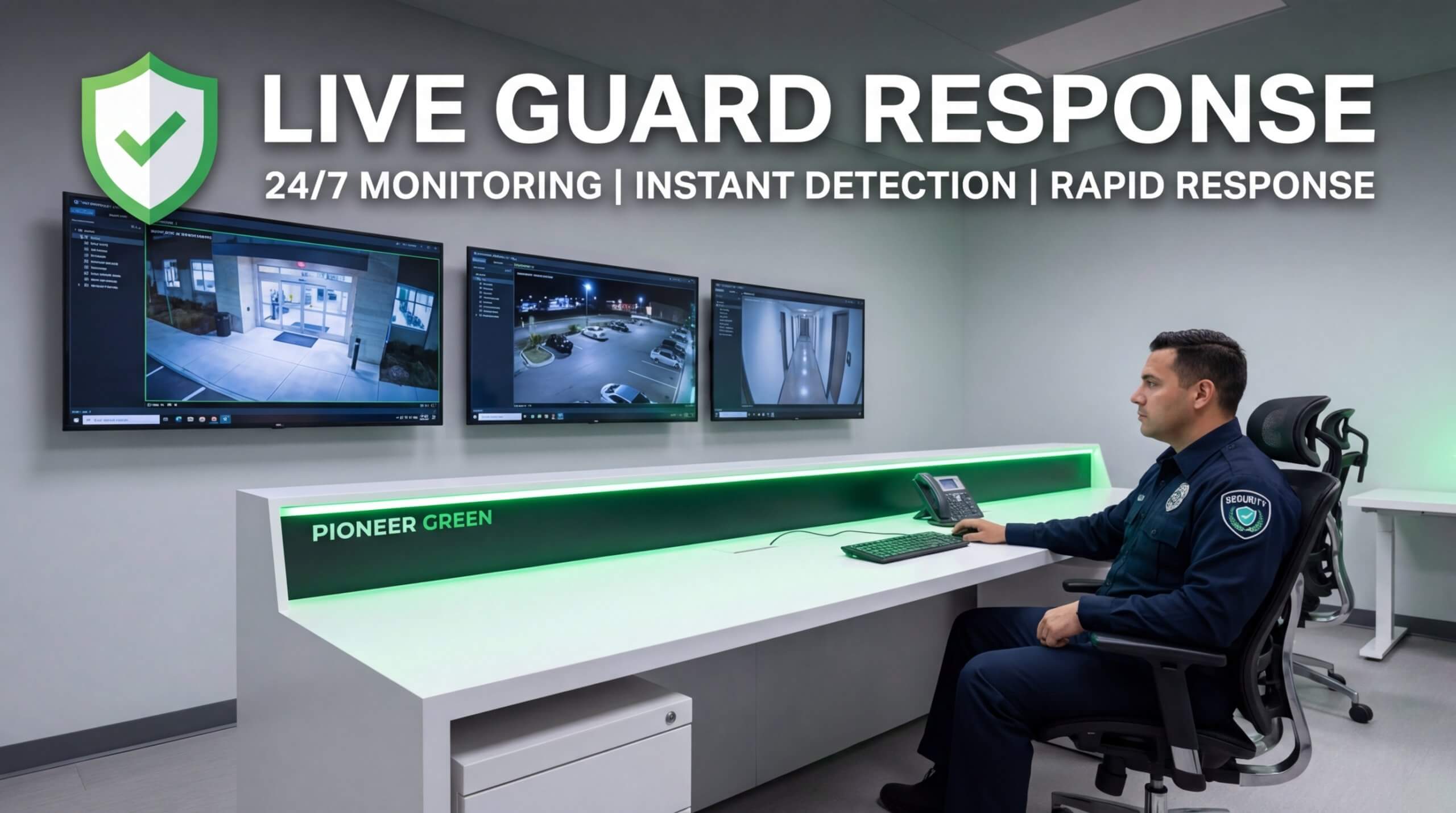
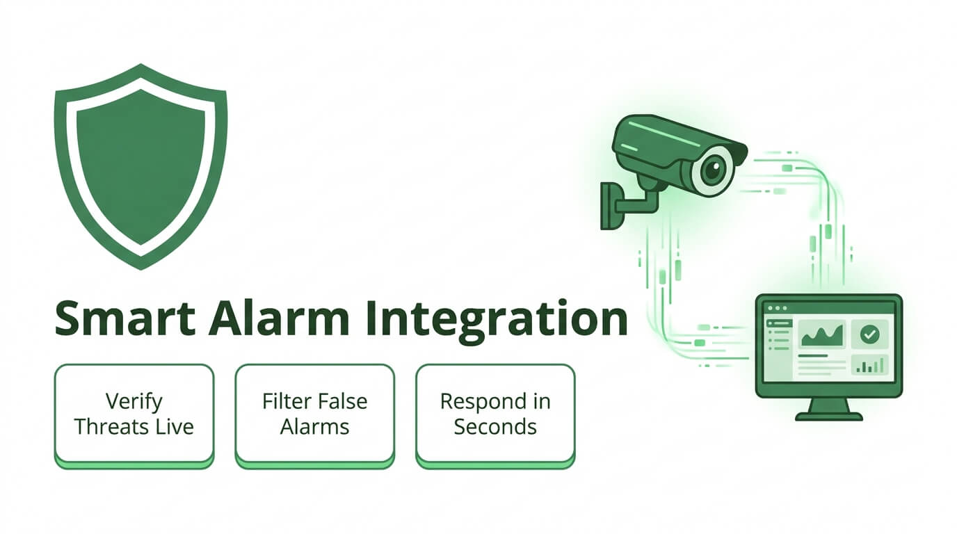
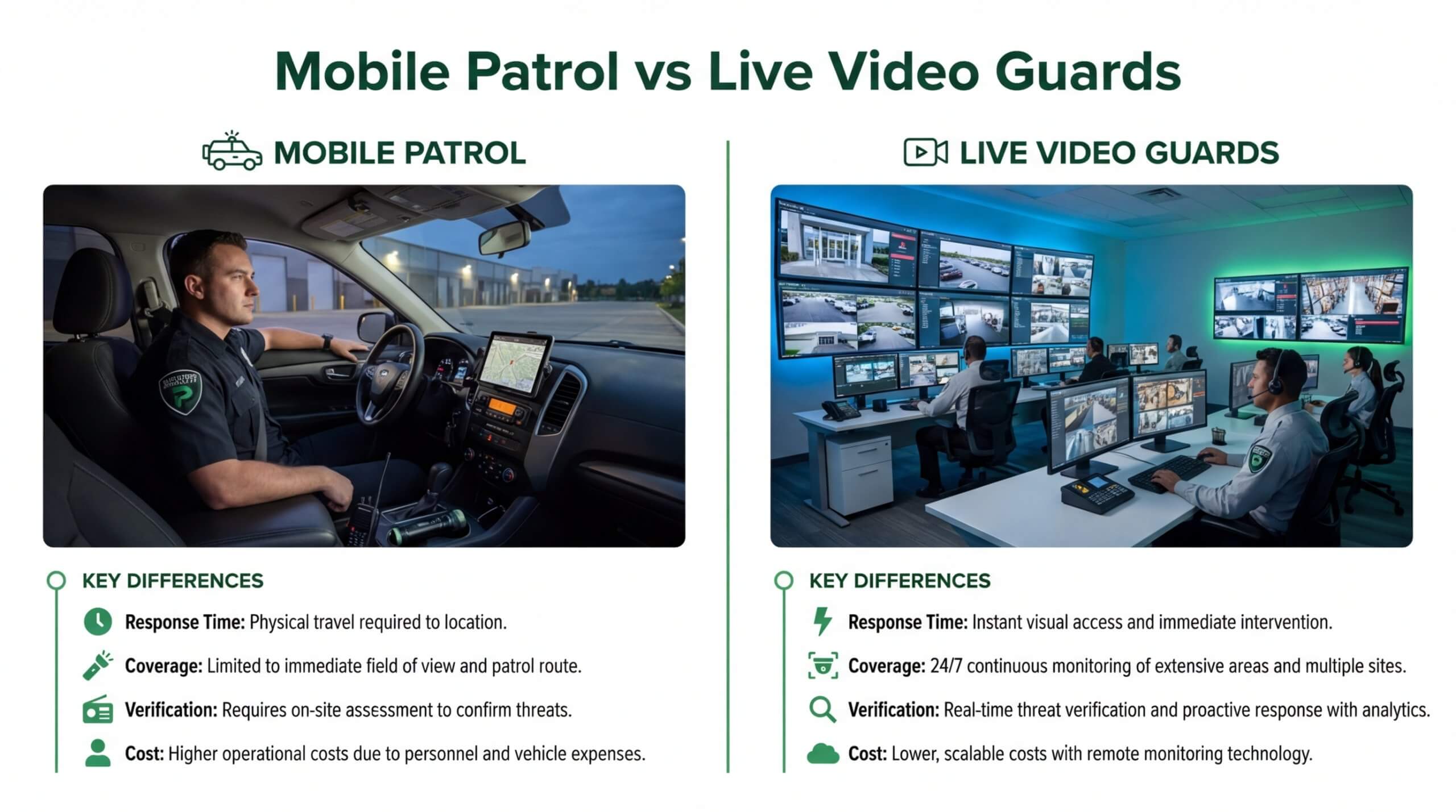
Yes, Pioneer Security’s live video guards can maximize your camera VLAN investment by pairing network-level isolation with real-time human intervention. A segmented VLAN protects camera traffic from unauthorized access, but the footage still needs active oversight to deliver security value. Pioneer Security combines AI-powered analytics with US-based live monitoring professionals who verify threats and respond through two-way audio before intruders enter a property.
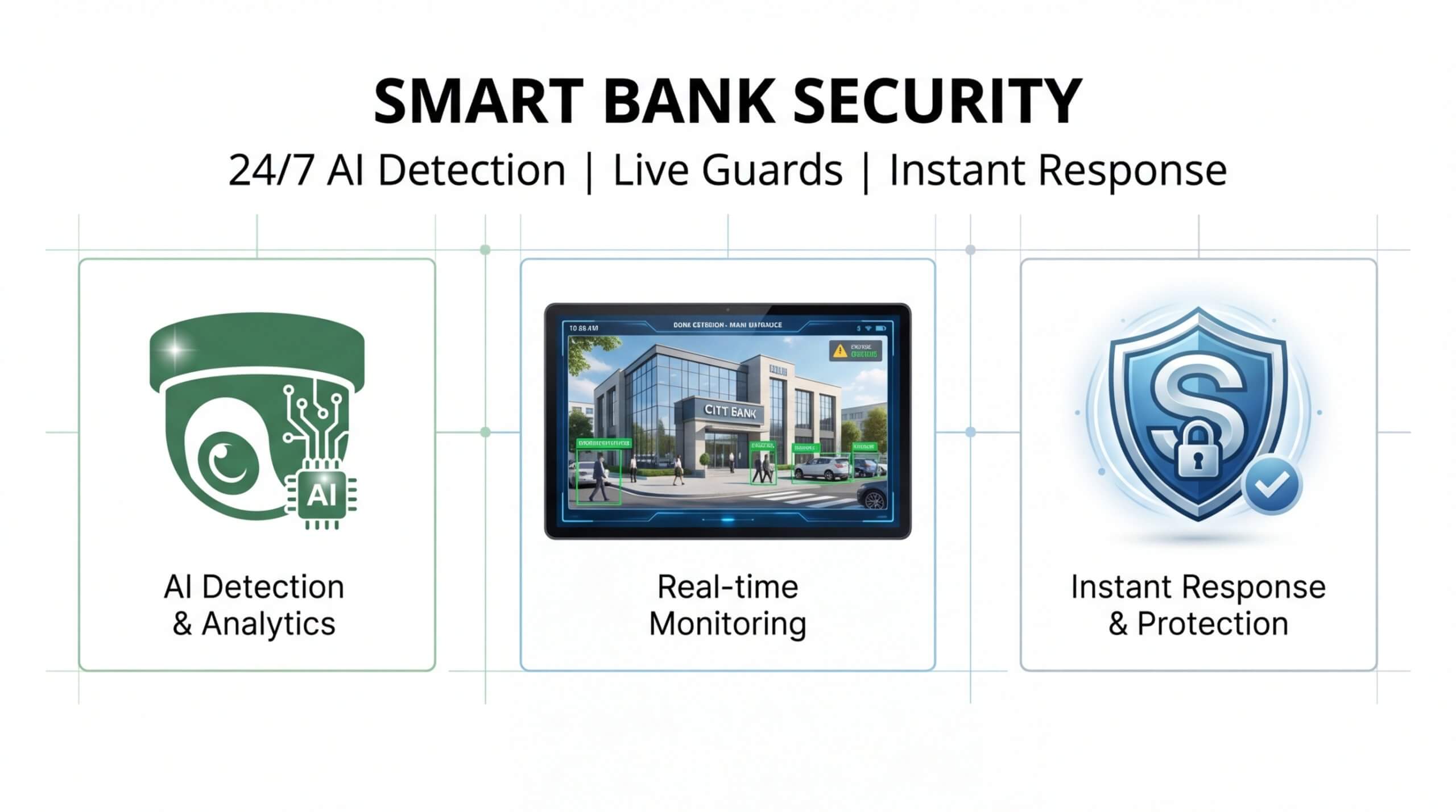
This layered approach matters because network hardware alone remains vulnerable. According to Forescout’s 2026 report, NVRs ranked among the top five riskiest IoT device types, alongside VoIP systems and printers. VLAN segmentation contains that risk at the network layer, while Pioneer Security’s AI-powered PoE hubs with Nvidia GPUs detect anomalies at the video layer. Together, these defenses transform cameras from passive recording devices into proactive crime prevention tools.
What Are the Key Takeaways About Setting Up a Separate VLAN for IP Cameras?
The key takeaways about setting up a separate VLAN for IP cameras are:
- VLAN segmentation isolates camera traffic from production networks, reducing attack surfaces and bandwidth congestion.
- Managed switches with PoE support, proper trunk port configuration, and dedicated subnets form the hardware foundation.
- Firewall rules should block internet access on the camera VLAN while permitting only NVR or VMS communication across VLANs.
- Static IP assignments and DHCP scopes prevent addressing conflicts after migration.
- Hardening measures like disabling dynamic trunking, enforcing host authentication, and monitoring for anomalies close common security gaps.
- AI-powered live video monitoring adds the human verification layer that network segmentation alone cannot provide.
A well-configured camera VLAN paired with professional monitoring delivers both cybersecurity resilience and real-time threat response, which is the standard every surveillance deployment should meet. Pioneer Security specializes in bridging that gap with AI-driven live video guards built to protect what your network infrastructure secures.